

Auto-Calibration
Auto-Calibration
HOME> Support Services> ATOM 2 Series> Getting Started> Auto Calibration
Automatic correction setting teaching
The latest firmware of Atom can memorize the value of the previous automatic calibration. If the machine is not changed, there is no need to recalibrate.
The following situations will require automatic calibration again:
● After the machine is assembled for the first time
● Moved over the glass platform
● Have dismantled the nozzle or mobile platform module
● Handling machine
Please follow the steps below to ensure smooth calibration of your machine.
Pre-preparation for automatic calibration
Before performing automatic calibration, you need to make sure that the mechanism is operating normally to avoid unnecessary interference so that the automatic calibration can be completed smoothly.
Please perform the automatic calibration after checking the following A~D:
A. Institutional inspection
1. Make sure that the side blowing fan does not touch the mobile platform to avoid calibration interference.
2. Confirm that the nozzle is firmly locked on the upper cover of the mobile platform.
3. Make sure that the cover on the mobile platform of the nozzle is locked flat and locked on the mobile platform.
4. Adjust the belt to normal tightness
5. If you are not sure about the inspection procedures of the institution, please click here to view the detailed pictures and texts.
B. Confirm whether the glass will shake
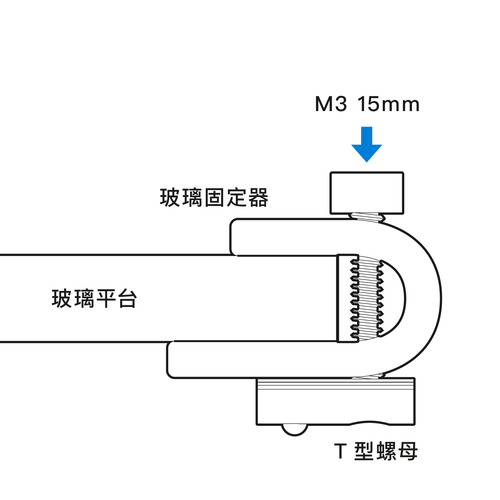
After locking the glass holder, shake it by hand to check that the glass will not shake to avoid affecting the automatic correction result
(For the detailed assembly steps of the glass of the hot bed kit, please refer to the assembly instructions provided by the original manufacturer).
C. Nozzle residue cleaning
If there is residual cooling PLA material left on the periphery of the nozzle, it will cause deviation during automatic calibration. It is recommended to perform the preheat function first and wait for 5 minutes to let the residual material pre-squeeze out, then take the napkin (do not use normal toilet paper, easy Sticky) Wipe off the residual material from the print head and start printing.
! Note! Do not touch the heated nozzle without any protective measures!
D. The distance between the limit switch and the screw
Note! Do not touch the heated nozzle without any protective measures!
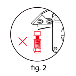
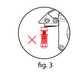
The calibrated limit switches are divided into mechanical and optical types. Please adjust according to your model and refer to the illustration below.
Atom 2.0 mechanical micro switch adjustment method
The screw should lightly touch the micro switch to minimize the distance affected by the stroke of the mechanism during each automatic calibration. In other words, the nozzle can be lightly touched to the platform. The lighter the better, if it is pressed too deeply, it will be easy to deviate. . To
If the screw touches the micro switch, but there is a jump during the automatic calibration, it may be that the cable set did not reserve the length when it was originally assembled, which affected the automatic calibration. At this time, you can tighten the screw 1/ 4 turns, or remove the hub first to minimize the interference of automatic correction.
Please see the picture below.
※ Please note: Do not use cable ties or tape to tie the hub to avoid inaccuracies caused by pulling.
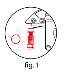
The screw just touches the micro switch
The screw just touches the micro switch
The screw just touches the micro switch
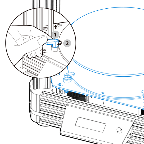
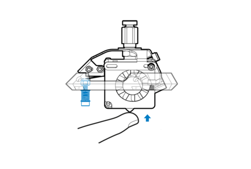
Atom 2.5 series optical limit switch adjustment method
The screw should be just shielded to the limit switch, so that the distance affected by the stroke of the mechanism during each automatic calibration is the least. In other words, the nozzle can be lightly touched to the platform. The lighter the better, if the pressure is too deep, it will be easy to lose. Deviation. To
If the screw is covered by the limit switch, but there is a jump during the automatic calibration, it means that the cable set may not have reserved the length when it was originally assembled and the automatic calibration may be affected. At this time, the screw can be tightened 1/ 4 turns, or remove the hub first to minimize the interference of automatic correction. As shown in the dynamic picture below, gently pushing up the upper cover part of the mobile platform will make the light turn on. To
※ Please note: Do not use cable ties or tape to tie the hub to avoid inaccuracies caused by pulling.

Steps for automatic correction
Please make sure to check the pre-preparation for automatic calibration according to the above list, otherwise the automatic calibration will not achieve the best results. We have also filmed the automatic correction instruction into a video, please follow the video below to start the setting (note that the video version is different).
Automatic calibration steps for firmware 2.0 series:
1. After clicking the knob to enter the menu, click [Setting Z Offset ].
2. Click [Auto Calibration] to perform automatic leveling.
* This feature is added to firmware 20180329 or later, if you use the old version of the firmware, skip it
3. Click [Bed Leveling] -> [Auto Level] to perform automatic calibration.
4. Selection [Go to Zero].
5. Put a piece of ordinary A4 paper (80P) between the print head and the glass platform, and observe whether the print head can rub the paper, and the paper can move back and forth without too much effort. There should be a little friction, but it doesn’t matter. To let the print head scratch the paper.
6. If the print head is too far away, please slowly lower the [Z-Offset] parameter and repeat steps 3~4.
If the print head is too close, please slowly increase the [Z-Offset] and repeat steps 3~4. Adjusting the value too fast will cause the operation to lag. Below is the instruction to adjust Z-offset.
7. After finding the proper distance, you can start printing, and there is no need for G29 command in Gcode.
Automatic calibration steps for firmware 2.5 series:
1. After clicking the button to enter the menu, click [Bed Leveling].
2. Click [Auto Calibration] to perform automatic leveling.
* This feature is added to firmware 20180329 or later, if you use the old version of the firmware, skip it
3. Click [Bed Leveling] -> [Auto Level] to perform automatic calibration.
※If the rod is dropped, you can remove the spring of the mobile platform cover before calibration. In order to avoid the use of this spring in the future, the metal elasticity of the cover of the mobile platform will become fatigued. Therefore, there was a tightness in the first few times. Cause the print head to fall off, it can be reinstalled after calibration and before printing.
4. Click [Adjust Offset].
5. Put a piece of ordinary A4 paper between the nozzle and the glass platform, and observe whether the nozzle can rub the paper, but the paper can move back and forth without any effort.
6. If the print head is too far away, please slowly lower the [Z-Offset] parameter and repeat steps 3~4.
If the print head is too close, please slowly increase the [Z-Offset] and repeat steps 3~4. Adjusting the value too fast will cause the operation to lag. Below is the instruction to adjust Z-offset.
7. After finding the proper distance, you can start printing.
How to adjust the correct Z-offset of the print head (Z-axis compensation value)

The print height of the print head can be adjusted directly from the LCD. After confirming that the paper is correctly touched (above) to A4 paper, you can start printing.

The print height of the print head is too high, and the paper can be easily pulled with one hand, which will cause printing failure. Please lower the Z-Offset until the print head touches A4 paper.
Print out the appropriate height
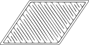
After performing automatic calibration, you can start to verify the set results. The first layer at the beginning is the most critical element; the correct arrangement should be as shown in "Figure 1". Each path has a clear texture, a stable output, and there is no gap between the outer and inner fillings. If it is printed with " In the case of "Figure 2" or "Figure 3", you can fine-tune the height of the nozzle.

Figure 1: Moderate height
The care path is neatly arranged on the bottom plate, and there is no gap between the inside and the outside.
There is a gap between the periphery and the inside, indicating that the nozzle is not locked, please click here to check the nozzle mechanism and re-check.

Figure 2: The nozzle is too high

The material cannot be smoothly adhered to the bottom plate, causing wrinkles and curling deformation. You can slightly tighten the screws in front of the print head and do an automatic calibration to reduce the print height.

Figure 3: The nozzle is too low
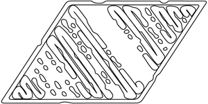
If there is no space for discharging, the print head will scrape directly to the bottom plate, and finally there will be lines in some places and no lines in some places. You can slightly loosen the screws in front of the print head and do an automatic calibration to increase the print height.
During automatic calibration, the nozzle hits the bottom plate
Please confirm whether the limit switch is working normally, please go through this (limit switch test). Make sure that the screw of the print head has been against the micro switch. When it touches the bottom plate, there is no room to release the originally touched micro switch, which will cause the phenomenon of hitting the bottom plate all the time. It is recommended to loosen the screw a bit (please click here to see how to adjust) before using Tap the nozzle from bottom to top to make a smooth click sound.
Nozzle jumps continuously during automatic calibration
The screw of the print head is too far away from the micro switch and it does not touch the micro switch. It is recommended to tighten the screw a bit (please click here to see how to adjust), and then use your hand to lightly tap the nozzle from the bottom up to make a click sound. can.
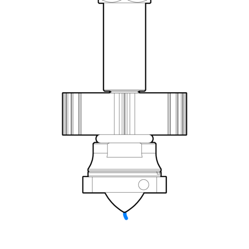
Z Min Error exclusion (2.5 series users)
When the print head sees the red light, it may cause the Auto Leveling to make a pressing sound and an error message. The following solutions are provided:

1. Pull the wire or PTFE tube to the upper cover, please remove the cable tie or the hub first. To
2. Turn the optical trigger screw upwards and lift the upper cover of the mobile platform. Please rotate the screw downwards until it emits red light again and then stop, and then turn it slightly upwards until the light disappears. To
3. The optical trigger screw has not covered the optical switch, please directly rotate the screw upwards until the red light goes out and then stop.
Can't solve the problem?