

Atom 3D printer problem
HOME> Support Services> Technical Support> Atom 3D Printer
The side blowing fan will not rotate
1. Check the control board circuit
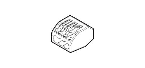
Check whether the part of the control board circuit has bitten the plastic skin but not the metal circuit. Please pay attention to whether the quick connector and the control board are indeed locked to the metal circuit.
2. Is there any magnetic interference from the carbon fiber rod
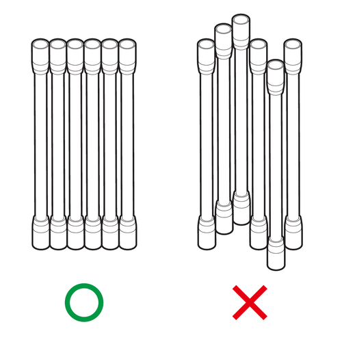
Since there are powerful magnets on the carbon fiber rods, the action of the side blowing fan will be affected by the magnetic force. It is recommended to remove all the carbon fiber rods and arrange them as shown on the left until the carbon fiber rods are aligned side by side, and then install them in order.
3. Is the side blowing fan "not yet" turning
According to our slicing software settings, the side blowing fan will not rotate at the beginning of printing, because the model must first be attached to the glass well. You can refer to the gcode file of 300mm Height, which is set to blow the fan only after the model is printed 3mm.
Reverse or abnormal movement of the sliding table
Abnormal movement: If you are a DIY model, please make sure that the wire color sequence of the stepping motor is correct or not connected properly. Since the whole model has been tested before leaving the factory, there should be no wiring errors.
If it is confirmed that the wiring is correct, try to replace the DRV8825 motor drive chip. It is possible that the chip is damaged and the motor moves abnormally. When executing the command of automatic calibration or returning to the origin, the three sliding tables must move at the same speed. If there is an abnormal phenomenon in one axis, please check the following:
1. Check whether the wires of the motor are properly connected to the circuit board.
2. Check whether the wire of the limit switch is properly connected to the circuit board.
3. Shut down and remove the power and USB cable. Exchange the wafer of the abnormal slide with the wafer of the normal slide, and then reconnect the power supply to execute the function of automatic calibration (Auto Level) or return to the origin (Auto Home). If the slide of abnormal wafer is changed to Abnormal, it means that there may be a problem with the chip, and it is recommended to perform a voltage check (below) If the voltage check is normal and the operation still appears abnormal, the DRV8825 chip may need to be replaced. Please refer to the following article: Measuring and adjusting DRV8825 chip voltage.
Reverse movement: If the movement direction of the three-axis sliding table is reversed (meaning it should move up but move down), please turn off the power immediately to avoid any collision!
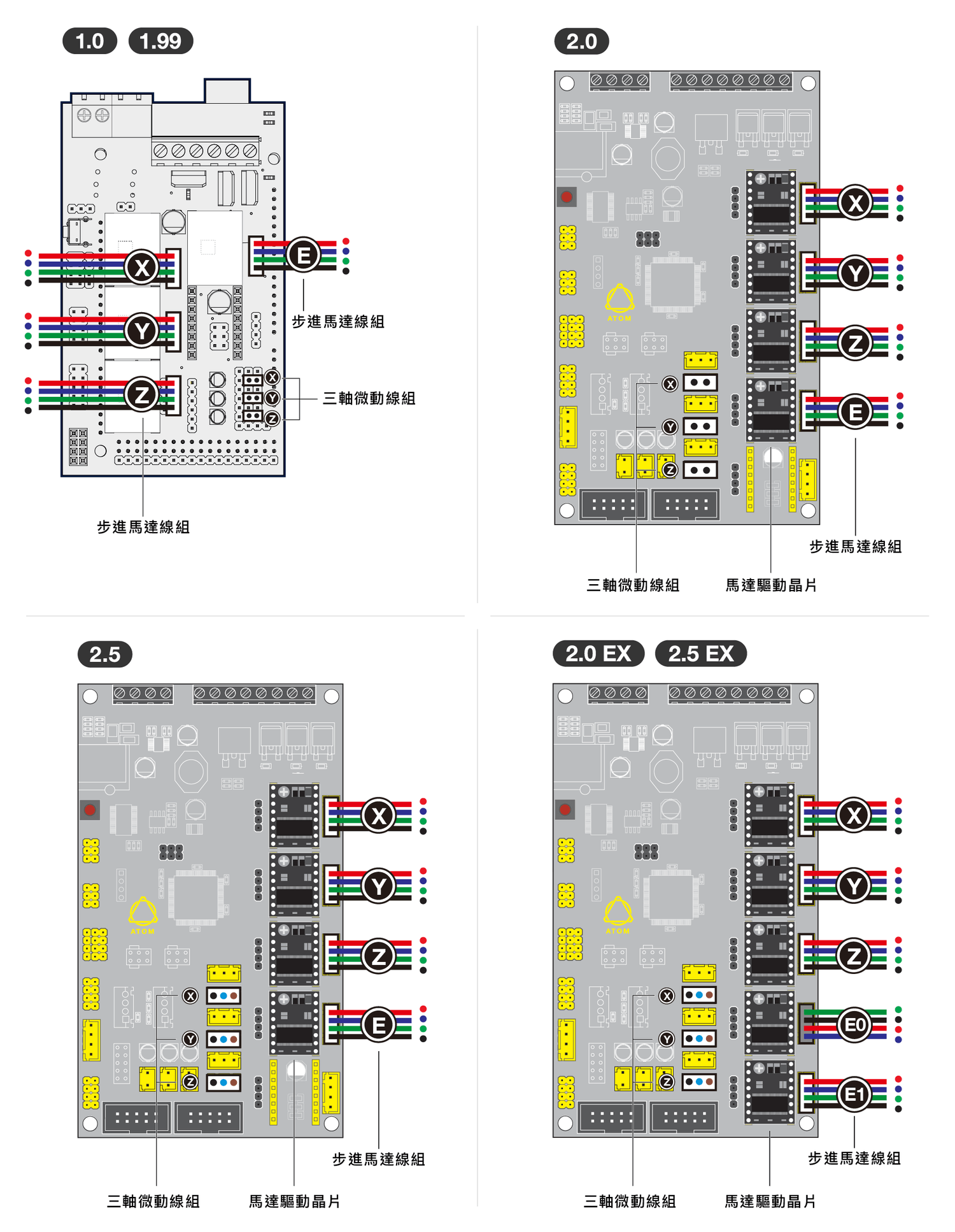
1. First check whether the installation direction of the cable is the same as in the manual, or you can refer to the picture provided below, please refer to the machine version on the upper left of the picture.
2. Check the direction of the DRV8825 chip, the screw end should be installed as shown in the figure, and then turn on the power after confirming that it is correct.
Cannot turn on or the LCD screen does not light up
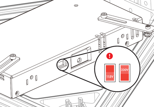
Please confirm the voltage of the power supply first, and adjust it according to the voltage of different countries (for example: Taiwan needs to be adjusted to 115V). To

Please make sure that the blue indicator light of the DC transformer is on.
If the nozzle fan of the printer does not run when it is turned on, it means that the printer is not overpowered. Please check the power supply according to the two icons above. If the power supply or voltage is abnormal, please replace it with another power supply and test whether it can work normally; if the power supply and voltage are normal, and the wires are also installed correctly, the control board on the machine may be damaged.
If the nozzle fan of the printer is running when it is turned on, it means that the printer has over power. If the LCD only has a blue screen at this time, it may be due to the following three reasons.
Remind you, when checking the circuit, please turn off the power first.
Condition 1-LCD failure
If the cable is not plugged in well or the cable is short-circuited, it may also be caused by the LCD itself.
Condition 2-DRV8825 failure
After unplugging the DRV8825 separately, see if there is a way to boot. If a chip can be booted after unplugging, it means that the chip is faulty and the chip needs to be replaced before it can boot normally.
Condition 3-short circuit
First remove all the connected wires, leaving only the LCD cable and 12V DC input, then turn on the power. If it can be turned on or the LCD display is normal, then connect the wires in order, and turn them off before connecting them. After connecting the power supply, turn on the power again until a certain line is connected back, causing failure to boot or the LCD screen does not light up, indicating that this line is short-circuited, causing the motherboard to enter protection measures and fail to boot.
Measure and adjust the voltage of DRV8825 chip
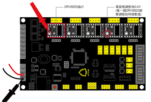
The chip DRV8825 is used to control the movement of the motor in each axis. The correct voltage is the key to accurate movement. The method of measuring the voltage of the DRV8825 chip is as follows:
1. Turn on the power of the printer.
2. Switch the three-way meter turntable to the two-digit voltage range.
3. Use the positive electrode (red) of the three-way meter to contact the metal screw head (Vref) on the DRV8825 chip.
4. Use the negative pole (black) of the three-way meter to contact the negative pole of the power supply terminal (connected to the black wire).
5. The way to adjust the voltage is to rotate the screw on the DRV8825 chip. When adjusting the voltage, please rotate it gently and slowly, because the screw on the chip is very sensitive. Set the value to 0.4V.
Power-on test-three-axis limit switch test
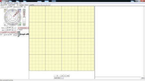
We can use the Pronterface software to issue commands to the Atom 3D printer:
1. Use the control button on the left side of the software to move the three axes of the machine or heat the nozzle
2. Input gcode via USB cable
3. Give instructions to the machine
Let us take you step by step to use this software.
1. Lower the three-axis sliding table to ensure that the limit switch is not touched.
2. Download Pronterface (please select your corresponding machine link to download)
3. Connect the computer with USB and turn on the power of the machine.
4. Install and execute Pronterface.
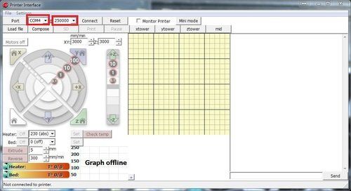
5. Select COM Port@250000
[How to find COM Port (in Windows), My Computer (right-click)> Manage> Device Manager> Ports COM & LPT> look for "USB Serial Port (COM ####)"], select @250000. To
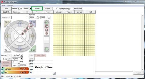
6. Click the [Connect] button. To

7. If the connection is successful, the text in the green box will be displayed. If there is no response, check the USB connection and the power switch of the machine, and click [Connect] again to try.
8. To test the limit switch, type [m119] in the field and press [Send] to send. To
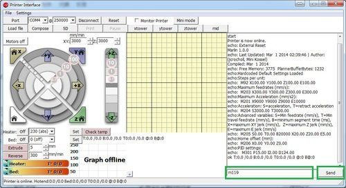
9. The words appearing should be the same as the following (open), which means that all the limit switches are in an untriggered state. If the words “triggered” appear, it means that the limit switches are abnormal. To
● X_max: open
● Y_max: open
● Z_min: open
● Z_max: open
If all limit switches respond normally, click the [Home] button.
If the limit switch is displayed as: triggered, please make sure that the limit switch is not in contact with anything. If the limit switch does not touch any insight, it still displays as: triggered, please check if the cable is correctly connected to the motherboard , Or check whether the wire at the end of the limit switch is welded firmly. If it is not the above problem, please check whether the wiring of the entire limit switch is complete. If a certain part of the line segment is damaged and causes an open circuit, it needs to be reconnected or welded. To
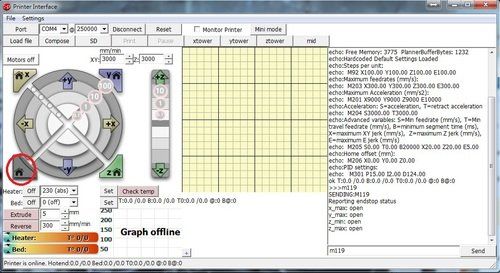
10. If all limit switches respond normally, click the [Home] button and wait for the three axes to move to the top.
11. Hit the [m119] command and press [Send] to send.
12. The screen display is as follows:
● X_max: triggered> X-axis limit switch
● Y_max: triggered> Y-axis limit switch
● Z_min: open> Print head limit switch
● Z_max: triggered> Z axis limit switch
Confirm that the limit switches of the three axes are pressed, and use your fingers to lift the nozzle end up and do not let go, so that the screws in the nozzle do not resist the limit switches. In the lower right corner of the dialog box, input [m119] and click [Send]. The following words should appear.
● X_max: triggered> X-axis limit switch
● Y_max: triggered> Y-axis limit switch
● Z_min: triggered> print head limit switch
● Z_max: triggered> Z axis limit switch
13. If all steps are confirmed to be correct, you can proceed to the next step. To
Can't solve the problem?