

Slicing technical support
HOME> Support Service> Technical Support> Slicing Software
Download and support
Now that the basic assembly and settings have been completed, you must be impatient to print your own work! You can download the KISSlicer software and configuration files in our download area, and click me to watch the configuration file input instruction.
About KISSlicer
KISSlicer is one of our recommended slicing software. A slice is a 3D STL model that can be converted into a .gcode file that can be read by a 3D printer.
Print for the first time with default settings
In this process you need:
● KISSlicer, please be sure to put it in a folder named in English
● Test print files downloaded from support
● SD card (format: FAT32)
● Windows or Mac computers that can run KISSlicer and read SD cards
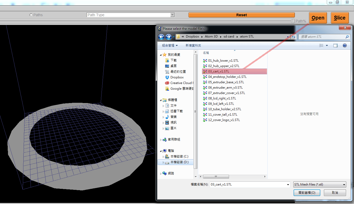
1. Run KISSlicer.exe, click [Open] in the upper right corner of the software screen, browse the downloaded file and select the cart.stl file, or you can drop cart.stl into the KISSlicer screen and open it directly.
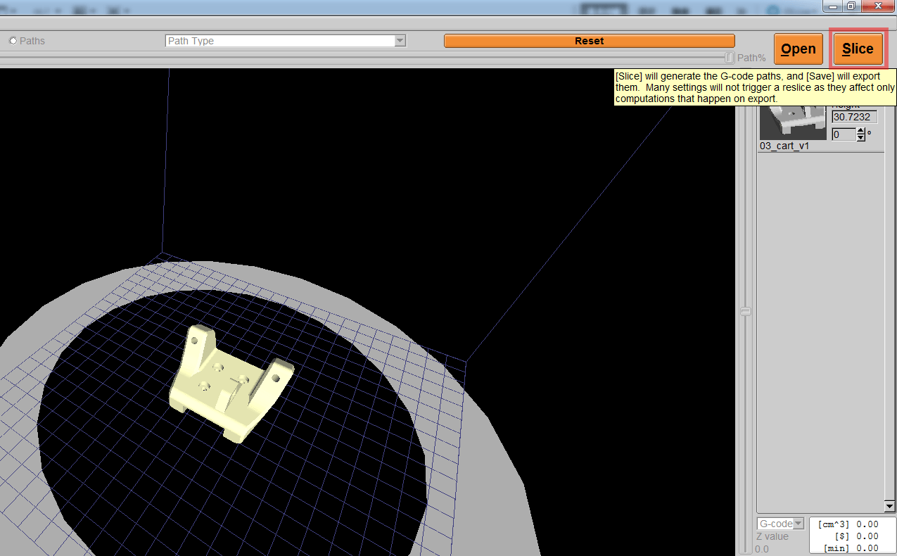
2. Click the [Slice] button on the upper right to slice.
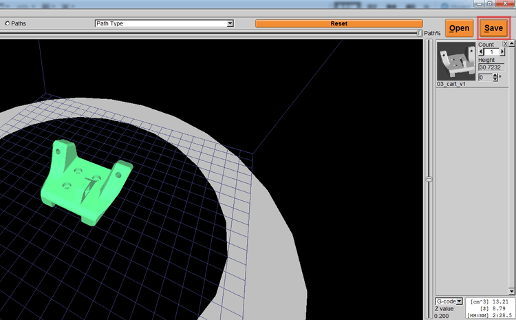
3. KISSlicer starts slicing, you can insert the SD card into the computer for use. Once the slice is completed, the [Slice] button will turn into a [Save] button. At this time, you can save the .gcode file in the SD Card (the SD card can read the files in the root directory or folder in the machine).
4. Insert the SD card on the side of the LCD screen of the Atom printer, and select [Print from SD Card] on the control knob.
5. Select the file [cart.gcode] and press the knob to start printing.
At the beginning of printing, the printer will start the [Auto Home] action, then it will drop to a certain height, and then begin to heat the print head, once it reaches a predetermined temperature, it will start printing.
Check the layer height of the first layer printed out and compare the printed results. The printing quality of the first layer is related to the overall printing quality. If the quality of the first layer is not good, it is recommended to re- Print, and may need to re-adjust the height of [Z-offset], you can refer to (Automatic calibration setting teaching) after adjustment, re-select the file to print.
KISSlicer interface introduction

KISSlicer detailed parameter description
Next, let everyone understand the meaning of KISSlicer's various parameter settings. The frequently used parameters will be marked with a red background in the following description, and detailed instructions will be attached. Most of the settings can be seen after re-slicing. When you move the mouse to the setting part during use, an English explanation will be displayed on the panel. You can also refer to the explanation. For other parts that are not specially marked, you can refer to the original settings provided, but we are also very happy for everyone to understand the meaning of each parameter setting. You can make different adjustments and print them out for a trial. In this way, you can also refine the slices. Understanding of software and Atom.
Style
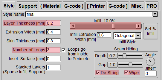
Layer Thickness
The layer thickness, that is, the resolution, is usually set to 0.2 mm, the thicker the printing, the faster the printing, and the relative surface fineness will also be affected. If you want to down-repair, 0.1 ~ 0.15 mm has a pretty good fineness, and 0.05 mm is fine. Print the model with the finest surface, but it will take longer to print.
Extrusion Width
Usually set the extrusion width similar to the diameter of the nozzle (nozzle diameter 0.4 mm), we will set it at approximately 0.3 ~ 0.4mm.
Skin Thickness
For this part, we usually set a value smaller than [Number of Loops] multiplied by [Extrusion Width].
Number of Loops
Usually 3 circles, the more circles, the longer the printing, the thicker the shell, and this part is not limited to [Skin Thickness].
Loops go from inside to Perimeter (path order)
When this option is checked, the outer circle of the printed model will be printed from the inside to the outside, which can avoid bumps on the outside of the model. Check this option.
Inset Surface
Enter a positive value to adjust the surface shrinkage. This function is very suitable when the printed item needs to be combined with other items, because the PLA material itself may be a little swollen during printing. Use this function. Make the item shrink inward as a whole (x, y direction shrinks, z direction will not shrink); otherwise, input a negative value, the item will expand outward.
Infill% (internal filling)
Set the density of the internal structure. When printing, you can choose to print the complete entity (100%) or use the internal filling setting to save printing time and reduce the consumption of PLA materials. The percentage adjustment can be adjusted depending on the item The size varies, general items up to 16.7% have enough strength.
Infill Extrusion Width (Infill Extrusion Width)
The setting is the same as the value of [Extrusion Width]. If you change this parameter setting, the inner filling and extruding width will be different from the outer width during printing. Usually the same value is set as the extruding width, but If the internal structure of the printing cannot be adhered tightly, the width of the inner filling material can be increased slightly.
Infill Style (internal filling shape)
It is divided into Octagonal octagonal honeycomb and Straight straight cross structure. Choose Octagonal. If you want to save time, you can choose Straight.
De-String (withdrawal)
Dragging is usually caused when the print head jumps from one point to another when printing, just like a thin spider web. It can usually be eliminated by using a lighter to overheat it, but this work usually feels tedious and troublesome. If it can be printed at the beginning It would be better to produce a complete printed product. Therefore, it is recommended to turn on the retraction function when printing to reduce the phenomenon of thread pulling due to residual material when the nozzle is moving.
Wipe (wiping material)
Wipe the material, before entering the next layer after each layer is printed, wipe the printed parts to ensure that there is no material on the print head, so that when jumping to the next point, it can also reduce the production of dragging. It is also recommended to turn on the wiper function when printing to reduce the phenomenon of thread pulling.
Support
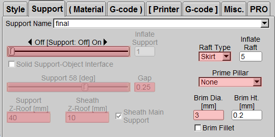
Support Density
Divided into Ultra, Fine, Dense, Medium, Rough, Coarse, usually use the loosest density Coarse. Inflate Support: Extend the range of support. If the support is very thin, you can use this function to allow the support to be generated on the bottom plate smoothly.
Inflate Support (Expanded Support)
Enter a value (unit: mm) to expand the support range. It is recommended that you can open it when the printed item is very small and increase the support area.
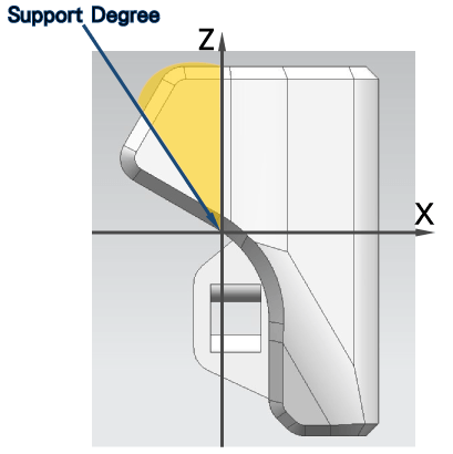
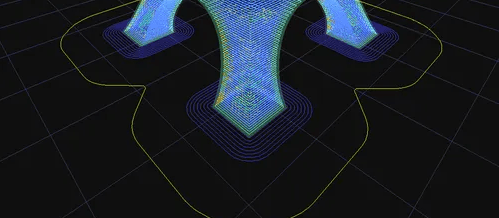
Support Degrees
The angle is the included angle with the Z axis. Take Figure 1 as an example. As long as the angle between the model and the Z axis exceeds the range of the yellow area (Figure 1), a support will be generated. When the side blowing fan is turned on, ATOM2.0 does not need to be turned on The support can print features that have an angle of more than 70 degrees with the Z axis (Figure 1), or it can print a short bridge without opening the support.
Gap (Support) (the distance between the support and the item)
If the distance between the support and the model is too close, it will be difficult to remove it when printed, and if it is too far away, the support function will be lost. Generally speaking, change it above 0.3. To
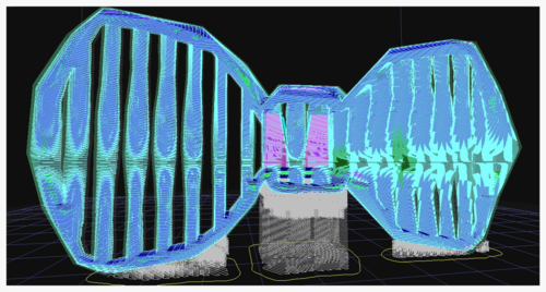
Support Z-Roof (support height)
Generally speaking, you do not want the support to cover the entire model. This function can limit the height of the support generation, so that it can be printed smoothly without collapsing, without affecting the appearance of the overall model. From the bow tie model (Figure 2), we don't want the long support inside the bow tie, so we can set a height to limit the height of the support.
Sheath Main Support (open auxiliary support)
When necessary, an outer frame may be needed around the support to avoid very thin and fragile supports that will shake during printing. Checking this function will have multiple exit glyph supports around the zigzag support. Increase the strength of the support. However, it is recommended that the height of this kind of support does not need to be set too high, as this kind of support may be difficult to remove.
Sheath Z-Roof (height of auxiliary support)
Adjust the height of [Sheath Main Support]. Only positive values can be input. It is recommended not to exceed [Support Z-Roof].
Raft Type (base plate support style)
Raft -> Grid (Figure 3 ): A base plate is grown under the model and the support material. This function is usually used to fix the support material or the model with a small base area to help it smoothly fix the bottom on the glass plate (but it is more difficult to follow. Remove), if it is a spherical model, we can also open the support to make the first layer of it smoothly formed.
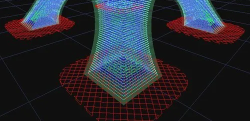
Raft -> Skirt (Figure 4): This function is to walk an outer ring around before printing the first layer, and continue to push the material out. It is a pre-discharge mechanism to ensure that the material can be printed when the body is officially printed Convergence. Usually, this function must be selected for each print, which can help to output the material smoothly at the beginning of printing.
Inflate Raft (distance from base plate support)
Expand the distance between Raft and the object (unit: mm). Generally, the built-in distance is set to 2mm, and the distance can be expanded as required.
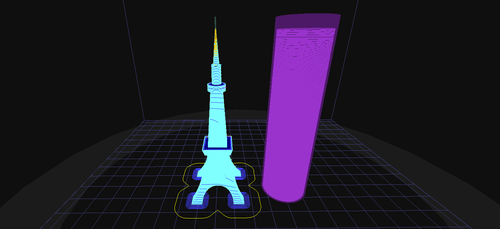
Prime Pillar
(This is a new feature in version 1.50) Can grow thin pillars: This feature is specially designed for printing small objects, such as the minaret feature in the picture on the right. Since the area of each level of the minaret is small, it is easy because the PLA has not cooled , The print head will then print, causing distortion and deformation; by turning on this function, the print head will print the pillars after completing the spire path, allowing time for the spire to cool down and fix it, so that the shape of the spire will be very complete.
Day denim.
A layer of bottom plate grows around the model and grows out several times. This function is usually used to print a model with a small bottom plate area. The auxiliary model can smoothly print the first layer on the glass plate. Because it grows around the model, It is easier to disassemble after printing than the grid function. It is better to set [Brim] about 5-10mm outward.
Brim Ht.
Set the thickness of [Brim] (unit: mm). If it is set to 0.2, only one layer of [Brim] will grow. Usually one layer is sufficient.
Brim Fillet
The periphery of [Brim] will be rounded.
Material
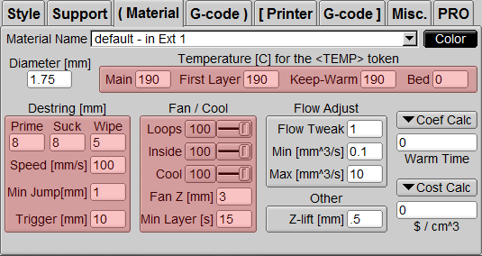
Diameter
PLA wire diameter, set 1.75mm.
Temperature
Main / First Layer / Keep-Warm: The temperature range can be changed with each machine and different materials selected, generally between 180 and 210 degrees.
[Main] is the main temperature, [First Layer] is the temperature of the first layer, and [Keep-Warm] is to keep the temperature at the set value.
Bed: see Heated Bed
Flow Adjust
Adjust the extrusion flow rate of the nozzle. Usually we will set it to 1 which is 100%. If the material used is not standard (1.75mm), this value may need to be adjusted. If the material is too fine or the output is insufficient, an increase of 5% may be required Therefore, enter 1.05, which can be adjusted as required. But you need to pay attention to whether the nozzle is blocked due to this adjustment.
Z-Elevator
After the destring is finished, when the print head is about to move, it will first lift a certain distance. If the object is a closed structure, it can prevent the print head from interfering with the printed part. But if it is a more open structure (for example, there are many holes), you can set this value to 0 to avoid wire pulling.
Destring
In [Style] you can set [De-string] to enable this function (p.25). Here, because each material has a different viscosity when it melts, it must be set according to the characteristics of the material to avoid wire pulling.
Prime: Push the retracted back again and set it to 8mm as well.
Suck: Withdraw/reduce the draw wire setting 8mm.
Wipe: When moving to the next printing area, it will wipe back a short distance, generally set 5~6mm, and small model is 2~3mm.
Speed: Set the speed of retraction and retraction, usually set at 80 ~ 120mm/s. Note that the setting of this value must not be set too large. If the retraction and retraction speed is too fast, it may affect the stability of the nozzle (Too fast may pull the nozzle platform). In addition, it should be noted that when using the panel knob to accelerate, the speed will also increase proportionally!
Min Jump: [Min Jump] means the [Destring] can be turned on when the distance between the nozzles is between two points. If the distance is less than the set value, the [Destring] and [Wipe] functions will not be turned on. The value is usually set to 0 or 1, but users can also set it according to their needs.
Trigger: [Trigger] means that the nozzle is between two points. When the distance is between two points, the [Destring] and [Wipe] functions must be turned on. The value is usually set to 10, but users can also set it according to their needs.
Fan / Cool
Adjust the speed of the side blowing fan, and you can adjust different values according to different parts of the printer. The value ranges from 0 to 100, 0 means turning off the fan, 100 means turning on the maximum wind speed of the fan, and the fan speed can be adjusted according to printing requirements.
Loops: Set the speed at which the side blowing fan runs on the outer ring.
Inside: Set the wind speed at which the side blowing fan fills the print interior, usually set to the same speed as [Loops].
Cool: Set the fan speed of the side blowing fan until [Min Layer].
Fan Z: When printing is higher than this height, the side blowing fan will be turned on with the set wind power. If it is turned on at the beginning, the wind may be too strong and the bottom layer may not stick. It is recommended to set this value to 1-3mm.
Min Layer: [Min Layer] (unit: s) limits the minimum time for each layer to print. This function is usually used to print thin objects. Since the upper printing layer has not yet cooled, the next layer will be laid directly , Resulting in uneven appearance and even printing failure. If you set it to 15 seconds, the layer that was printed in 5 seconds will be changed to 15 seconds because of our setting, so that the print has time to cool down. However, too long a time will cause the nozzle to move too slowly and cause heat to accumulate at the same point. Generally, we will make adjustments in 10-20 seconds. In addition, there is a little trick. We can add a simple model next to the small object when printing, or let the small object have more time to cool down (such as the Prime Pillar function in the support column).
Printer
Printer / Hardware
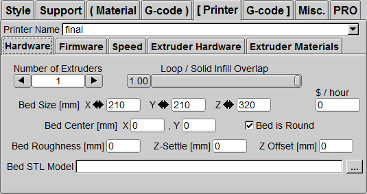
Bed Size
Set the print range, X:210 Y:210 Z:320 (this is the machine print size).
Bed Center
Set X=0 Y=0
Bed Roughness
The flatness of the printing platform is set to 0.
Bed Is Round
Tick to enable this function, and the printing platform of Atom is circular. To
Z-Settle
The improved parameter of the printing platform similar to the Maker bot structure is set to 0 because we don’t need it.
Z Offset
The initial printing distance of the first layer is the same as the concept of "Z 0.3" in the command G29 Z 0.3 ;. If you do not change this paragraph, the printing height of the first layer is still too high or too low, you can set it :
The print head is too high and the material is hanging in the air: Z Offset -0.1
The nozzle is too low and pressed to the platform: Z Offset 0.1 for fine adjustment.
Bed STL Model
The file of the printing platform floor model is in the setting file in the download area. To
Printer / Firmware

Firmware Type
Choose 5D-A bsolute E as the extruder.
File Extension
Type gcode for the file extension when generating.
Mark Path Start/Stop
None
Include Comments
Checked
Post-Process
(Empty)
Fan On
Enter the fan turn-on command: M106. To
Fan Off
Enter the fan shutdown command: M107. To
Fan can do PWM
Tick.
Printer / Speed

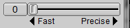
Fast & Precise Speeds
These two settings are for adjusting the detailed parameters of printing. The setting of Fast (Lower quality) is the detailed parameters of printing when the speed is fast, and the setting of Precise (Slower) is the detailed parameters of printing when the speed is slow. For convenience To use, there is a speed adjuster on the right side of the setting window (as shown below) to directly set the printing speed.
Solid Infill Support
The speed of printing internal filling and support, Fast (Lower quality) is set to 30; Precise (Slower) is set to 15.
Sparse Infill
To print the looser internal filling speed, set Fast (Lower quality) to 30; Precise (Slower) to 30.
X, Y Travel Speed
The running speed of the print nozzle without extruding material is set to 80.
Perimeter
Print the peripheral speed, Fast (Lower quality) is set to 30; Precise (Slower) is set to 5.
Z- Speed
The moving speed of the printing platform in the vertical direction (Z axis) is set to 100.
1st Layer Max Speed
The maximum speed when printing the first layer is usually set to 10 so that it is relatively slow but stable after the first layer is printed. The perfect printing of the first layer can lay a good foundation for subsequent printing.
Limit Increase / Layer
After printing the first layer, the speed of the printhead platform will increase until [Perimeter], [Solid Infill Support] and [Sparse Infill] reach the set speed. Setting a value of 5 can make the printing of the previous layers more stable And precise.
XY Accel
The acceleration in X direction and Y direction is set to 3000.
Printer / Extruder Hardware
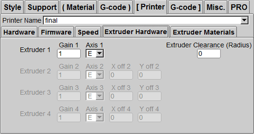
Extruder 1 / Gain 1 / Axis 1
Gain 1 is set to 1, and Axis is set to E. To
Extruder Clearance
Set to 0. To
Printer / Extruder Materials
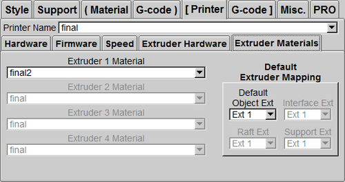
Extruser 1 Material
Set the edited material name in [Material].
Default Object Ext
Set to Ext 1.
G-Code
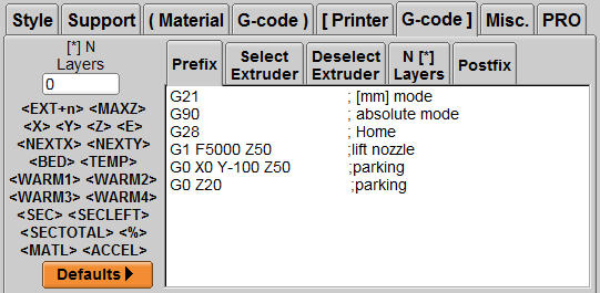
G-code / Prefix (actually execute the action before printing)
G21; Set the printer to [mm] as the unit
G90; Set the printer to absolute coordinate mode
G28; Execute the reset action, which is equivalent to the LCD menu [Auto Home] function
G1 F5000 Z50; Quickly move the nozzle to Z direction height 50 mm
G0 X0 Y-10 0 Z50; Move the print head to positioning heating
G0 Z20; Move the nozzle to position heating
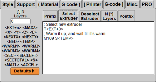
Select Extruder (Select Extruder)
T ; Select extruder
M109 S ; Set to start printing after reaching the preset temperature.
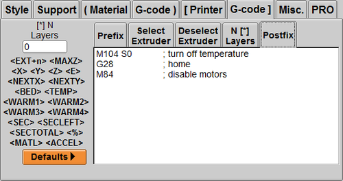
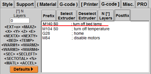
Postfix (action executed after printing is finished)
M104 S0; stop heating nozzle
G28; execute return to origin function
M84; Stop power supply to all stepping motors. To
Heated Bed Heated Bed Setting
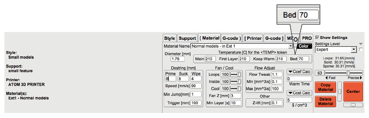
Temperature | Bed (heated bed)
This step is for users who have installed the Atom heating bed kit.
1. Set the [Bed] temperature in the Temperature parameter setting (applicable temperature for common wires: PLA 70℃; ABS 100℃)
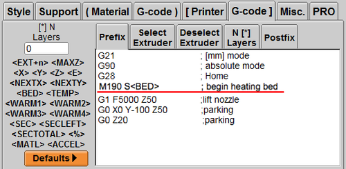
2. Type M190 S in Prefix ; begin heating bed
3. Type M140 S0 in Postfix; turn off bed temp
4. You can start the heating bed. For other 3D printing parameter settings, please refer to other settings in this chapter.
● The heating bed can not use lipstick glue or special printing tape to strengthen and fix the printed parts.
● When the heating bed is operating, please do not touch the bottom plate and other parts to avoid burns!
● When using the heated bed, do not leave for a long time. If you must leave, turn off the power to avoid danger.
● It is recommended to use a separate socket. Try to avoid using extension cords or sharing sockets with other electrical appliances. To
Can't solve the problem?